Slot cars
Overview
We got Brain Slot Cars working at Maker Faire 2012.
Two player racing was done at Westport Mini Maker Faire 2013 by using two laptops, each one receiving data from a headset and controlling individual tracks.
Two player video: [1]
We may try to implement electronic traction control for slot cars to break speed records.
How we did it
First step was to get a meter and make sure these slot cars used analog control with a DC voltage. The power brick was rated for 14.5vdc, and the measured voltage was about 20.5 - no problem.
Next was to figure out the pins on the power track. There are four 3-terminal card edge connectors - two of which are for the power brick, and the other two for the controllers. The two power connectors have reverse polarity, but they weren't keyed in any way, so it would be possible to plug them in the wrong way. The controllers were simple rheostats, and the third pin was connected to a 22Ω 2 watt resistor. We never figured out what that was for.
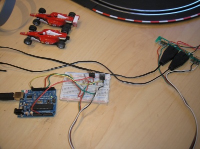
We replaced the controllers with MOSFETs. We chose MOSFETs because of their power handling capability and low on resistance. Since we were switching the high side (the low side was wired directly to the track), we used the track through the car as the virtual "ground". A P-Channel MOSFET might be a better choice, but this works fine.
The gate of the MOSFET then went to an Arduino, so we could use the AnalogWrite command to PWM the desired speed to the cars.
From there, Guan did his magic and wrote a sketch for the Arduino to take commands from the serial port, and a Processing sketch to interpret brainwave data and generate the serial commands, and we were off to the races!
Electronic Traction Control
The trick here is to take a 3" long car, and detect when the wheels are losing traction. We could use a gyroscope chip to detect the turn rate, and if the turn rate of the car starts to exceed the turn rate of the track, we back off the motor speed. On straightaways we set the throttle to max.
Brain Slot Cars instructions
On the slot car power section, there are 4 groups of contacts, each with 3 contacts. From left to right, they are connected like this:
- N/C
- Drain (MOSFET 1) +
- Source (MOSFET 1) -
- Power connector, the label should say + -
- Power connector, the label should say - +
- N/C
- Source (MOSFET 2) -
- Drain (MOSFET 2) +
There is no direct connection between slot car ground and Arduino ground because the MOSFETs are used as high side switches.
On the Arduino, the source of both MOSFETs are connected to ground. The gates are connected to PWM enabled pins. In the sample sketch, use pins 5 and 6. Pin 5 is supposed to be connected to the outer track, pin 6 to the inner track. (This matters because the outer track should go faster.) The outer track is attention, the inner track is meditation.
The Processing sketch will display debug messages from Arduino. In the Processing sketch, first select the serial port for the Bluetooth headset (only one for now), then the serial port for the Arduino. "Poor signal" should be 26 or 0 for a good skin contact. 255 means there's no connection to the headset at all. 200 usually means we are talking to the headset, but there's no skin contact. 51 indicates poor skin contact.
If there is an initial error connection, it's probably because the Bluetooth headset is not paired or the Arduino is not plugged in.
