Interactive Automaton
Introduction
This is a proposal for the big group project for 2013. It's an interactive art display that uses movable hexagonal modules that communicate with each other. The modules will constitute a cellular automaton. Each module has white or RGB lights and will change its color/lighting/blinking based on its own state and the state of its neighbors. The modules are mounted on a board and guests can move around the modules and change its rules using pushbuttons or touch buttons.
This is best spoken of as a 3D reconfigurable version of Conway's game of life.
Name
Ideas:
- Color Life (Guan)
- The Automaton (Guan)
- Life (Guan)
- Carbon Based Life (Robert)
- Color Tube (Guan)
- Triad (Antonio)
- MegaNanoTube (Dave)
Plan
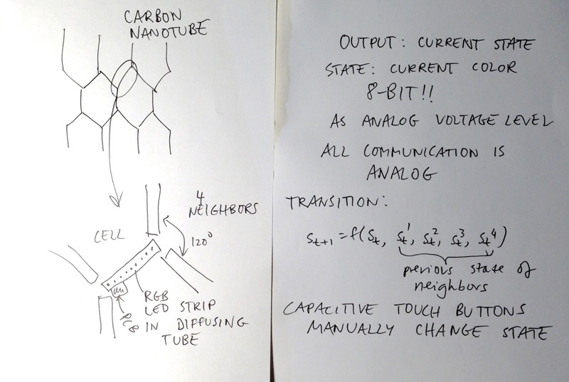
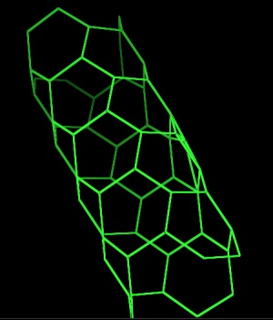
The structure is carbon nanotube. Each vertex connects to 3 edges. Each edge connects to 4 other edges, 2 on each end.
Each edge is a cell, consisting of a piece of waterproof Chinese 5050 RGB LED strip, perhaps 3 LEDs (5cm) or 9 LEDs (15cm).
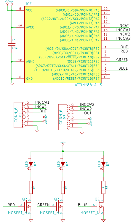
Each edge is controlled by a PCB with an ATtiny261 class microcontroller and 3 MOSFETs.
Each edge lights up in a color from a prespecified 8-bit color space. It signals its color to the 4 neighboring edges with analog signaling, 256 different voltage levels for the 256 different colors. It has 4 analog inputs, one from each of the 4 neighboring edges.
At each clock (perhaps once per second), the edge reads the 4 analog inputs. Its state (color) in the next clock cycle is a function of the 4 inputs. (This function could mutate!)
(We would need both 5V and 12V power rails throughout the structure.)
Preliminary simulation videos
There is a fixed rule. In each round there is a small probability that an edge randomly changes color.
One color alternative
The organic "Game of Life" nature of the structure might be too complicated by adding colors. Conway's game would be complicated if it were RGB. Possible solutions:
- Very well specified transition functions, for example where each edge's color in the next period is the average of input colors in this period + noise.
- Use a single color throughout.
Connectors and connections
Each edge is a cell. Each edge is connected to 4 other edges, one at each end.
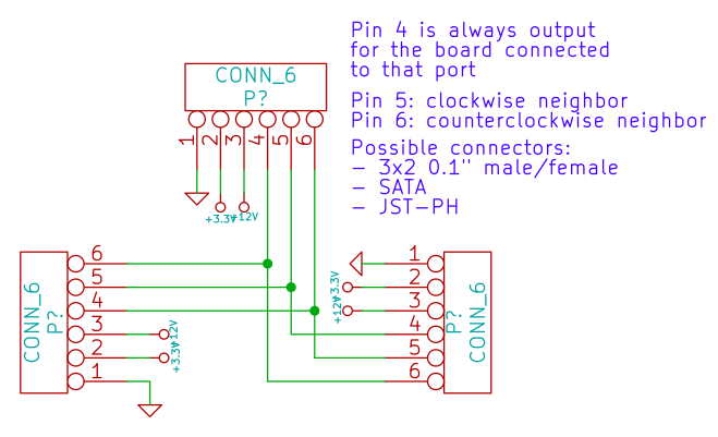
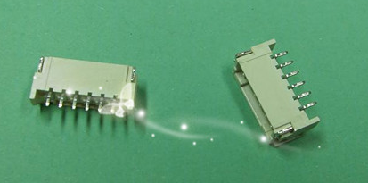
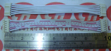
Each vertex forms the junction of 3 edges and can be seen as a 3-channel analog bus. There will be a PCB at each vertex with the following schematic. All connections are made by 6-pin connectors and cable assemblies. Each edge PCB will have 2 6-pin connectors. The pinout, from the point of view of the edge PCB:
- Ground
- 3.3V (or 5V if we go with that)
- 12V
- Transmit
- Receive from clockwise neighbor at vertex
- Receive from counterclockwise neighbor at vertex
Possible candidates for connectors: 3x2 0.1" like AVR programming, 1x6 0.1" ribbon, IDE cable with extra connections for power, SATA connector. We will pick whatever is cheapest.
Edge (cell) design
Dumb display mode
In addition to the autonomous cellular mode described above, we could implement a dumb display mode where each pixel is individually addressable from a central computer. This could be used for all kinds of fun things:
- Any kind of game can be played on the display
- Visitors could stand in front of a webcam, and the display would show an 8-bit version of what the camera sees
- Visualize music or sound
- Have a 3D scan consisting of 3 or more webcams pointed at a given location, do 8-bit visualization on the CNT cylinder
If we don't care about having the electronics reflect the cellular structure of the game, we could possibly save a lot of money by only having the dumb display mode.
Design
Frame
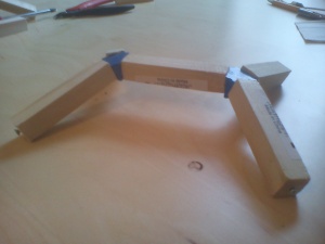
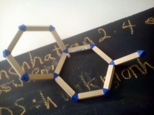
Update: now built! http://t.co/NQCTOeXENL
Needs some hot glue to reinforce for electronics mounting and transit process.
- Flat frame
- Mounted on PVC buckyball
- Buckyball has 60 vertices
- Large triangular PCBs with holes in them for attaching plastic rods for the edges
- Prototype of a dowel/3D connector frame
- 7.5 cm pieces of 5/8" poplar dowel, with a #4 wood screw driven into each end. Allows clip-fitting and removal of each module, and a little out-of-plane distortion. Plastic connector can be given explicit angles as desired. Could take a long time to 3D print a few hundred, so maybe some sort of injection moulding?
- Alternate design could have a retaining bolt perpendicular to the rod through its end; this might also be stronger but would take a little longer to fit together.
Updated version of 3D printed connector
Previous versions did not have the correct angles to form a proper nanotube of the desired radius. They didn't print well, and took a long time to do so. They also didn't account for an unanticipated twist along the plane of the bond for some bonds. Therefore, a redesign (which also increases stability of the joints).
For a [3-3] (armchair) configuration of nanotube, the predicted bond angle is 116.93 degrees. From this, one can use trig to calculate the vertex angle at the apex, which works out to be 150 degrees. The remaining angles in the triangle bisecting the tetrahedron are 20.1 and 9.9 degrees, the latter of which is the angle used in the new connector. Angles were confirmed by generating a 3D model nanotube.
For 1.4 A bond lengths, 96 bonds gives a tube of length 13.5 A, diameter 4.3 A.
So for a bond length of 7.5 cm, with 96 edges, we get a tube of length 73 cm, diameter 23 cm, requiring 8 x 36" 1/2" dowels @ $1.77 each (Lowe's).
PCB BOM
@100
- ATtiny $0.57
- 3x BJT $0.10
- Passives $0.05
- Connectors $1
- Manual assembly
- Board $0.50
- RGB LED strip $0.50
$2.76
We are going to use a 700mV Vce bipolar transistor to save money.
ATtinyx61A is the same price @100 as the older ATtinyx61.
Vertex board:
- Passives $0.05
- Connectors - 0 (included in price above)
- Board $0.50
Total $0.65
Example:
- 100 edges
- 67 vertexes
- $320
All these prices are probably an upper bound because once we source components in China the component prices will come down.
Note: For dumb display mode, a second output pin has to be connected bypassing the RC filter so we can have high speed digital communication.
Connector
File:EPH.pdf: 2mm 6-pin JST PH. Samples (20 connectors and 10 cable assemblies) have been ordered. The price is $0.5277 each for 200 sets of 2 connectors and 1 cable assembly, which is suitable for 100 edges.
Output
- White LED
- RGB LED standard (easier to drive, more components) or WS2811/WS2812
- Sound?
- 2-color LED
Red LED:
- heartbeat 1 blink
- startup 2 blinks
- advance to neighbor state 2 blinks
- calibrate 3 blinks
- randomly advance 4 blinks
- neighbors are the same randomize 5 blinks
Connections
- Infrared
- Electrical - 8-bit PWM, for 8-bit color! (Analog for added noise)
Power
- Battery
- Power backplane
GPIO count
Assuming WS2811/WS2812:
- 3 data inputs
- 3 data outputs
- 1 for LED
- 2 for user input
Total: 9
Assuming RGB LED:
- 3 data inputs
- 3 data outputs
- 3 for LED
- 2 for user input
Total: 11
Assuming each pair uses a single data line with a pullup (can we use a pullup on a PWM line?):
- 3 data lines
- 1 for RGB LED
- 2 for user input
Total: 6
Possible microcontrollers
CPLD
Could we do the whole thing on a CPLD? An XC9536XL (TQFP-44) is $1.18. Would make it very easy to drive WS2812.
The only problem is that a CPLD needs external clock lines. Clock requirements for WS2812 are 160 kHz or multiple hereof.
- 555 timer - 50 cents to implement? Enough for 8-bit PWM.
- Global clock line
A single global clock line and have very interesting interactions because of the delays. It would be simplest in this case to skip PWM and only do 3-bit color.
ATtiny2313
SOIC-20, $0.672 @100
2 timers, 2 external interrupts, 2 ADC channels, 17 GPIOs
ATtiny261
SOIC-20 or TSSOP-20, $0.986 @100.
ATtiny861 is $1.276 @100.
Possible pin allocation:
- PA4, PA5, PA6, PA7 analog inputs from neighbors
- PA0, PA1 capacitive touch 1
- PA2, PA3 capacitive touch 2
- PB4, PB6 capacitive touch 3
- PB0, PB2 capacitive touch 4 or indicator LED
ATmega168P
TQFP-32, $1.566 @100
LPC1114FBD48/302,1
TQFP-32, $2.2255 @100
All in discrete logic?
Probably too expensive if it can be done in a CPLD.
Status/subprojects
LEDs
Will RGB LED strip be bright enough in sunlight? We must test. We could put it under a canopy.
PCB based capacitive touch sensor
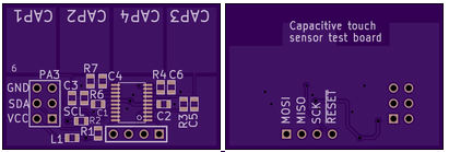
Validation test board based on ATtiny861 ordered from OSH Park, will arrive 2013-03-19. Parts are already here.
The board tests different bottom layer ground pour coverage ratios.
Edge board design
Awaiting capacitive touch sensor validation.
6-pin JST-PH connector samples ordered, will arrive by 2013-03-25.
State transition functions
Guan and Jason are experimenting with a Processing simulation.
Software/Firmware
https://github.com/hackmanhattan/life
Links
FIGMENT 2013 HM Logistics
FIGMENT Event Info
In 2013, FIGMENT will be open to the public on Saturday and Sunday 8/9 June 2013 from 10 AM to 6PM each day.
- http://newyork.figmentproject.org/more/artist-faqs/
- http://newyork.figmentproject.org/figment-nyc/faqs/
- http://newyork.figmentproject.org/figment-nyc/what-to-bring/
Load In List
http://newyork.figmentproject.org/figment-nyc/what-to-bring/
We will need people to help bring the following items to Governor's Island so that we can set up and staff the HM exhibit successfully - please add to this list if you think of anything else we might want to have during the event, or anything that would improve the aesthetic of the exhibit as a whole.
- Interactive Automaton (~ 3x2", a box to contain this will help a lot of anyone can find one?)
- ATX power supply (maybe a spare too)
- Basic tools for structure/electronics repairs - Soldering irons, hot glue, etc)
- Laptop/AVR programmer
- Spare 3D printed connectors, dowel and replacement connectors/boards
- Gazebo
- Table for automaton
- Chairs or other seating (beach towel? tarp?)
- Sign/poster with hackmanhattan.com and/or link to explanation of project on wiki, and short explanation of background and use of installation (i.e. how to interact)
- Clipboard to collect emails for HM mailing/announcements list
- Snacks/Drinking water
- CLEAR modem+wifi router
- Power Extension cords (splitter+orange 50ft)
HM Event Staff Signup
It would be best if we can have at least a couple of people at any one time watching over the exhibit and helping/talking to visitors about the project and Hack Manhattan. You don't need to sign up for the whole weekend, any help is gladly accepted! Help will particularly be needed early Saturday morning to help carry materials on the 1 train down to South Ferry Station, and at the end of the event Sunday evening.
Please indicate your availability to help with the exhibit here: http://www.doodle.com/q6wxtue4n4i64ytz
