Cicada Tracker
Introduction
Update: We're organizing a build party where you can build this kit on Saturday, April 13.
Cicada Tracker is a WNYC project to crowdsource soil temperature data to track the cicadas that will emerge in 2013. Their version has:
- Arduino
- Breadboard
- Thermistor mounted at the end of a wood dowel wrapped in plastic
- 9 LEDs to display thermistor temperature
The 9 LEDs display temperature using an encoding scheme that is robust to reversal.
Because it is based on kits available at Radio Shack, it costs $80. This is a version that costs less than $20.
The kit is based on the ATmega328P microcontroller, which needs to be programmed. If you are familiar with Arduinos, you can use the Arduino as ISP. We prefer the much faster AVR Dragon programmer. You can also bring in your chips to Hack Manhattan to be programmed. Contact Guan Yang for more information.
Breadboard version
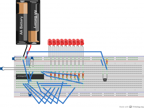
Fritzing file including breadboard diagram and schematic: File:Cicada.fzz
Schematic: File:Cicada schem.pdf
The breadboardable version has a BoM cost of $16.10 @25.
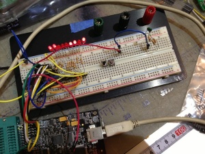
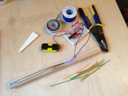
Prototype on bench, without the wood dowel part:
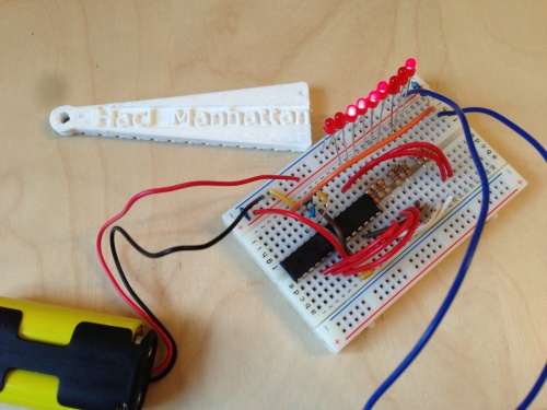
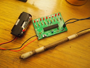
Final version:
Bill of materials
Unless otherwise noted, components and part numbers are from Digi-Key. We will soon have kits for sale at Hack Manhattan.
| Part | Quantity | Supplier | Part Number/notes |
|---|---|---|---|
| ATmega328P microcontroller | 1 | ATMEGA328P-PU-ND | |
| 10µF ceramic capacitor 0.1" spacing | 1 | 445-8287-ND | |
| 0.1µF ceramic capacitor 0.1" spacing | 2 | 399-9777-ND | |
| 0.1µF ceramic capacitor 0.2" spacing | 1 | 490-5401-ND | |
| Red 3mm LED | 9 | 4684620264 | |
| 220Ω resistor | 9 | CF14JT220RCT-ND | |
| 47kΩ 0.1% resistor | 1 | 47KADCT-ND | |
| 50K 1% NTC thermistor 7" wire leads | 1 | 317-1378-ND | |
| Solderless breadboard | 1 | 438-1109-ND or 438-1045-ND | |
| Jumper wires | Assortment, different lengths | ||
| Wood dowel | 12" | Blick | 60448-1212 assortment |
| 2AA battery holder | 1 | BC22AAW-ND |
Arduino sketch changes
We use a slightly different thermistor and pulldown resistor, so you need to find these lines in the Arduino sketch:
   const float B = 2700;
   const float R0 = 50000;
   const float T0 = 298.15;
   const float expected_resistance = R0 * exp(B * (1/273.15 - 1/T0));

   /* If you change the pulldown resistors change this. */
   const float pulldown_resistance = 50000;
And change them to:
   const float B = 3950;
   const float R0 = 50000;
   const float T0 = 298.15;
   const float expected_resistance = R0 * exp(B * (1/273.15 - 1/T0));

   /* If you change the pulldown resistors change this. */
   const float pulldown_resistance = 47000;
You can also find the correct Arduino sketch for this version in WNYC's Git repository.
- Dave has made a 'mobile' version, which will wait until the temperature stabilises before displaying the encoded temperature. This allows the dowel to be used in several places rather than being left in the ground
Hexfile download
The following hexfiles can be used if you are programming chips directly with an AVR Dragon or similar programmer:
- File:Cicada-50k-47k-3950.hex - 50K thermistor with B=3950, 47K pullup
Choosing a thermistor
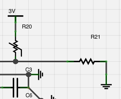
A thermistor is a resistor whose resistance changes with temperature. Thermistors have a wide variety of uses. In this case we are using NTC thermistors, whose resistance decreases with temperature, to measure temperature. To measure the resistance, we put the thermistor in a voltage divider circuit in series with a high precision resistor:
By measuring the voltage at the junction between the two resistors, we can know the resistance of the thermistor. Any value of resistor could in principle be used. For the colder temperatures found in soil, we typically select a resistor roughly equal to the value of the thermistor.
Thermistors are characterized by a variety of parameters and the temperature at 25 degrees Celcius. The bill of materials specifies a 50K thermistor, but any value from around 10Kohm to 2Mohm can be used. If the resistance is too low, the circuit will use too much current, and in fact thermistors below 1K or so are not actually designed to measure temperature, but rather for surge protection. This Digi-Key search will provide some suitable thermistors that are in stock.
PCB version
The PCB version must be soldered and has a BoM cost of less than $8.48 @25. It requires an additional on/off switch, Digi-Key part 450-1609-ND.
Note: Our first batch of PCBs have a solder mask error, so the switch has to be placed on the bottom and soldered from the top.
Components
- D1–D9: Red LED
- R1–R9: 220 ohm current limiting resistor for LED
- R10: 10K 1% resistor
- C1, C3: 0.1uF ceramic capacitor, 0.1" lead spacing - yellow
- C2: 0.1uF ceramic capacitor, 0.2" lead spacing - long leads, light blue
- C4: 10uF ceramic capacitor - shorter leads, dark blue
- R11: don't populate (for FTDI)
- C7: don't populate (for FTDI)
- SW1: must solder from top, 3 position pin header
