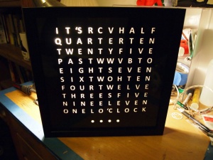
Charlieplexed WordClock
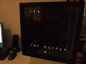
I wanted to make a Word Clock but customize it for my own requirements. I originally wanted to use a WWVB module for atomic clock setting, but the signal in my apartment on the East Coast wasn't good enough for it to work reliably. I also decided to use Charlieplexing instead of shift registers, just for the challenge, but also because it lets me easily change the face layout as required.
Inspiration
Instructable; printed transparencies, wax paper diffuser)
A commercial Word Clock; minutes indicators
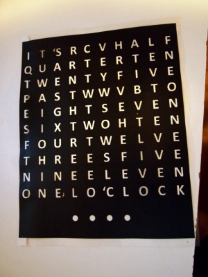
Face Lettering
A utility is available to calculate the optimal square (or other shaped) layout for any word set.
I ended up going with a design similar to this one but making the grid myself in a spreadsheet (see zip file below), then pasting into a graphics program and inverting the image colors.
The face design was laser printed onto transparencies (3 copies) at Staples for 50 cents each, which was sufficiently opaque in the black portions when all 3 are layered together.
Frame
IKEA OLUNDA frame. $12.99 (or similar RIBBA frames in other sizes).
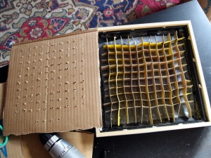
LED mounting and baffles
mount = Recycled Cardboard Box; free
baffles = cereal box cut to 1/2" strips cut halfway every lettergap spacing.
Charlieplexing
Arrangement of LEDs
10 x 10 charlieplexed array of 5 mm Ultra Bright LEDs, 17000mcd, 20mA continuous, 50mA peak current (fcb_electronics); $9.25/100
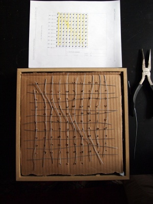
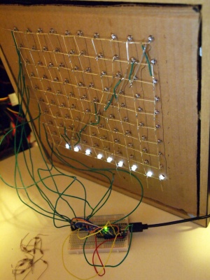
Wiring of LEDs
Finally made sense of making a square one after looking at other Charlieplexed layouts. This one really helped. See the datasheet for diagrams. Pairs of horizontal and vertical rows and columns are connected, and each pair feeds to a single digital out on the Arduino (see below). Digital pins 2-12 were used for the charlieplexed array.
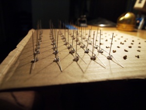
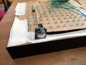
Originally I was going to solder together some wire buses, but lhe legs were just long enough for each 'bus' line to be contructed entirely from the LED legs. One leg of each LED is folded over the other at 90 degrees:
Initial breadboarded version to check the connections:
The four 'minute' indicator LEDs are powered individually as normal LEDs with a resistor, each from its own digital out (actually the first four analog outs on the Arduino).
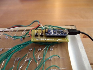
The Arduino is an Arduino Nano v3, from dx.com; $13.
I soldered some headers onto a bit of spare protoboard and added a couple of simple button circuits for DST setting:
Software
To get the 10 x 10 matrix to work, I modified the original Charlieplexing library for LOLShield by Jimmie Rodgers. This entailed changing the pin assigment matrix, and other variables relating to the matrix size.
The modified library and the Arduino code used to run the clock are in the following zip file:
Most of the code comes from Doug Jackson and Scott Bezek for a shift-register version, and I converted it to use the Charlieplexing and RTClib code. The RTClib library is from Jeelab, via Adafruit.
Realtime Clock Module
The RTC module is a DS1307 board from dx.com, for $4.80.
The I2C Clock (SCL) and Data (SDA) lines are connected to A4 and A5, the I2C-specific pins on the Arduino. The code sets the RTC module time to whatever the host PC time was on compilation and upload of the code.
